| |
| Technical Data of Motor Starting Reactor |
| |
| Motor Staring Reactor |
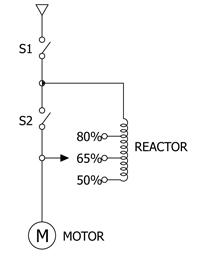
| Motor Starting Reactor is a device to reduce terminal voltage of an induction motor. As a rotary device in stop status starts and accelerates, its current reduces and terminal voltage increases to full start (after t seconds). At this time, the reactor is short circuited so as to operate the motor at full voltage. By limiting a starting current, this reactor is able to help a motor start smoothly and prevent a voltage drop induced accident at the time of wrong operation or start of a device. |
| |
| Product Features |
| |
With a rise in the motor speed, the terminal voltage of the motor increases and accelerates. Along with it, starting torque automatically goes up. Therefore, this product starts easily and has low mechanical shock.
This product features simple control and economy, and is able to increase or decrease a starting current with the installation of tap.
At the time of start, this product does not cause harmonic waves and protects motor insulation. |
|
| |
| Operation Principle |
| |
If S1 is injected at the time of its start, reactor is connected with motor in series. After start completion (t seconds), S2 is injected so that the product runs in full-load current.
In operation state after start completion, reactor has no current flow. |
|
| |
 |
| |
| Technical Data of Motor Starting Single-Winding Transformer |
| |
| Motor Starting Single-Winding Transformer |
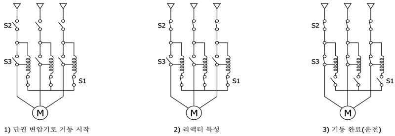
| With the use of the principle of single-winding transformer, motor starts. After start completion, neutral point is opened without separation of single-winding transformer. As a result, single-winding transformer works as reactor. At this time, if tap is short circuited, rated voltage is supplied to motor for start. In this method, when tap voltage is converted to full voltage, power is not separated from motor. Therefore, a shock is reduced and start torque of load gets large. For this reason, it is used much to start a large motor. |
| |
| Load that need single-winding transformer start |
| |
If start torque of load is large
If power capacity is small
Load equipment with large influence of voltage fluctuation
If fly wheel is large |
|
| |
| Operation Principle |
| |
With regard to S/W process, in the condition where S1 is turned ON, if S2 is turned ON, start should be performed by tap voltage. After start completion, S1 should be turned OFF.
If SI is not turned OFF after start completion, the product is damaged. Be careful. |
|
| |
 |
| |
| |
| Technical Data of Series Reactor for Condenser |
| |
| Series Reactor for Condenser |
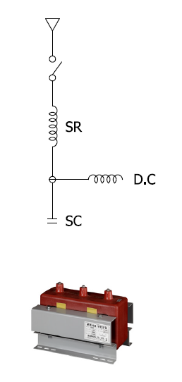
| This product is inserted in the condenser for phase advancer or condenser group (low voltage, high voltage, and special voltage) in series. The purpose of this series reactor is to reduce distortion of circuit voltage waveform and control inrush current at the time of condenser injection. |
| |
| Harmonic wave occurrence sources of power system |
| |
Load of rectifier and various converters
Rotary device
Loads of acr furnace and various electric furnaces
Transformer
Fluorescent lamp, Mercury lamp, and TV
Welding machine |
|
| |
| Effects of harmonic wave |
| |
If a harmonic wave is included in a current, copper loss, iron loss, device overheating, and noise occur.
If a harmonic wave is included in voltage, various failures, such as lowering withstanding voltage or insulation destruction, iron loss, increased noise, increased current loss, and increased charge current, occur. |
|
| |
| Harmonic obstacle to device |
| |
Overload of condenser
Loss (overheating) of rotary device and transformer and capacity reduction
Overheating loss of the condenser for protecting fluorescent lamp noise and safe device
Error of malfunction indicator of protective relay |
|
| |
| Reactance for harmonic wave occurrence sources |
| |
The inductive circuit with the 5th harmonic wave existing in power system 6%
The circuit with the 3rd harmonic wave of electric rolling stock load and arc furnace load 13~15%
Large rectifier and load welding machine (depending on an occurrence amount) 8~13% |
|
| |
| Technical Data of Discharge Coil |
| |
| Discharge Coil |
| It is always applied to both low voltage and high voltage condensers for phase advancer. The purpose of this discharge coil is to discharge residual charge in a short time when condenser is opened from circuit. |
| |
| Performance |
| |
Discharge capacity: less than 50V of condenser terminal voltage five seconds after discharge start
Insulation resistance: more than 500MΩ
Max use voltage: 24-hour mean is less than 110% of rated voltage. |
|
| |
| Connection type |
| |
General & Reactor Built-in |
|
| |
 |
| |
| Technical Data of Reactor for Inverter |
| |
| 인버터용 리액터(Reactor for Inverter) |
|
| Specification(사양) |
|
|
|
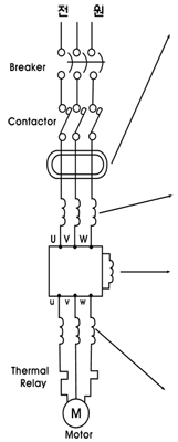
| Attachment Position(취부위치) |
|
Name(명칭) |
|
Application Criteria(적용기준) |
|
 |
|
(1) Video for reduction
Reactor |
|
 If Radio Noise becomes an issue, it is applied as reduction If Radio Noise becomes an issue, it is applied as reduction
measures. |
|
|
|
|
|
(2) Current for power
coordination Reactor
|
|
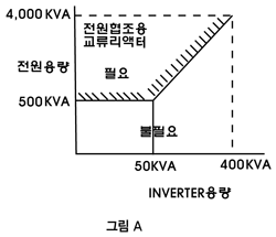
If the capacity ratio of power transformer is in the range
shown in Fig. A, it is needed.
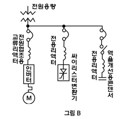
If Thyristor is turned ON-OFF with the same power, see Fig. B.
If Condenser for power factor control on the power side is
turned ON-OFF, see Fig. B.
If there is more than 3% unbalance of power voltage |
|
|
|
|
|
(3) Direct Current Reactor
(DCLA)
|
|
If the ripple of rectified DC waveform is removed or power
factor is improved |
|
|
|
|
|
(4) Alternating Current
Reactor (ACLA2L.H)
for noise reduction
|
|
Starting with Inverter causes unique large noise and vibration.
Therefore, connect AC Reactor in between Inverter and Motor
to make motor sound quality smooth and lower torque ripple.
(Noise 3-5dB reduction) |
|
 |
|
 |
|
|
|
| |